 Enes Guven
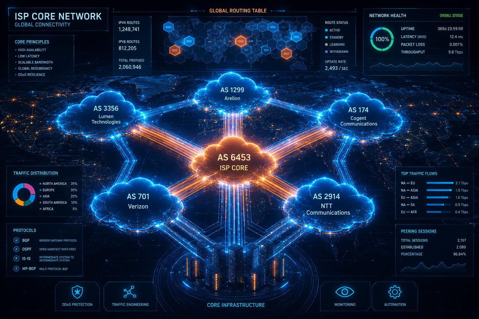
Designing an enterprise network is about connecting users to applications. Designing an Internet Service Provider (ISP) Core Network is about building the internet itself. In the carrier-grade realm, we abandon default routes and simple topologies; instead, we manipulate the flow of massive global traffic using advanced dynamic routing, strict traffic engineering, and hardware-level isolation.
This technical log delves into the true mechanics of an ISP backbone. We will dissect the intelligence of BGP Route Reflectors, the absolute traffic isolation provided by MPLS L3VPNs and VRFs, the necessity of sub-second stateful convergence, and the internal ASIC architecture of high-end chassis handling Terabits of throughput.
1. BGP Architecture & Route Management
At the edge of the ISP, peering with Tier-1 providers or Internet Exchange Points (IXPs) is handled via External BGP (eBGP). Here, the router ingests the full global routing table (currently exceeding 950,000 IPv4 prefixes). However, distributing this massive table to every internal core router via Internal BGP (iBGP) presents a severe architectural challenge.
By protocol design, an iBGP router cannot forward a route learned from one iBGP peer to another iBGP peer (the split-horizon rule). Maintaining a traditional full-mesh topology across a large backbone imposes immense memory and CPU overhead on the TCP stack and BGP process, as the router must generate and maintain discrete update groups for every single peer.
The enterprise solution is the implementation of Route Reflectors (RR). Provider Edge (PE) routers operate as Route Reflector Clients, establishing sessions only with a resilient Route Reflector cluster. To optimize memory allocation and update propagation, ISPs implement Route Target Constraint (RTC - RFC 4684). Instead of the RR flooding all VPNv4 prefixes to all PEs indiscriminately, RTC ensures that the Route Reflector only advertises specific VRF routes to the PEs that actively import those specific Route Targets, drastically minimizing the BGP RIB footprint on edge devices.
Security at the Edge: To mitigate BGP Route Hijacking, ISPs mandate RPKI
(Resource Public Key Infrastructure). This involves cryptographically validating
Route Origin Authorizations (ROAs) before installing a prefix into the RIB. Additionally,
volumetric DDoS attacks are neutralized at the ingress edge using Remotely Triggered
Black Hole (RTBH) routing via predefined BGP Communities (e.g.,
65000:666). When the monitoring system detects an anomaly, the target IP is tagged
and advertised back to the edge peers, dropping malicious traffic at the perimeter before it can
saturate core uplinks.
2. MPLS, VRF & Traffic Engineering
An ISP backbone carries traffic for thousands of corporate customers, many of whom use
overlapping private IP ranges (like 10.0.0.0/8). How does the ISP prevent these
networks from colliding?
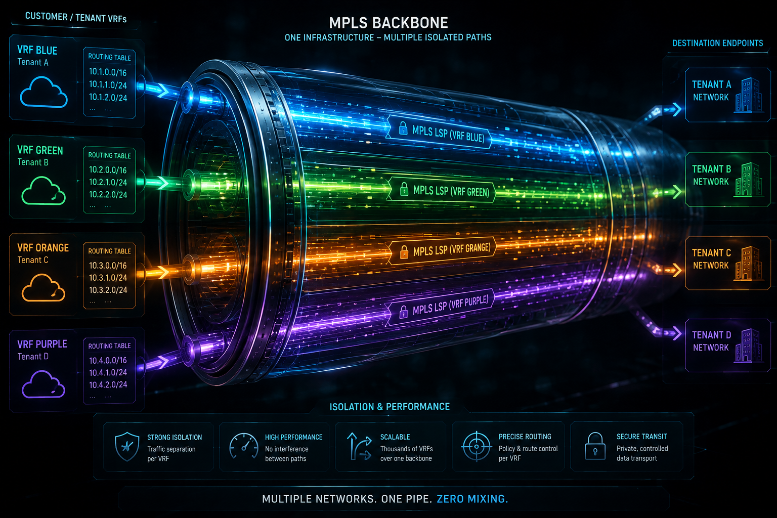
The answer is VRF (Virtual Routing and Forwarding) coupled with MPLS L3VPN. A VRF creates an entirely separate, virtualized routing table within the physical router. To make identical IP addresses unique across the entire core, a 64-bit Route Distinguisher (RD) is appended to the IPv4 address (creating a 96-bit VPNv4 address).
When Customer A's traffic traverses the core, it is encapsulated with MPLS labels. Route Targets (RT) act as import/export tags, ensuring that the traffic originating from Customer A's VRF on Router 1 can only be injected into Customer A's VRF on Router 2. The core routers (P-Routers) in the middle don't even inspect the underlying IP headers; they simply perform label swapping (LSR operations) at wire-speed based on their LFIB (Label Forwarding Information Base).
PE-Router-01 # configure terminal
PE-Router-01 (config) # ip vrf CUST_A_FINANCE
PE-Router-01 (config-vrf) # rd 65001:100
PE-Router-01 (config-vrf) # route-target export 65001:100
PE-Router-01 (config-vrf) # route-target import 65001:100
PE-Router-01 (config-vrf) # exit
3. Carrier-Grade Redundancy & Sub-second Convergence
In a carrier network, High Availability (HA) means far more than just having a secondary device. When the primary routing engine or firewall chassis experiences a critical fault, the transition must be entirely stateful and completely invisible to end-users.
To achieve this, clustered edge and core devices utilize dedicated high-speed heartbeat links (e.g., 40G or 100G DAC connections). These data channels continuously mirror the internal session table, active IPsec Security Associations (SAs), and dynamic NAT port blocks from the primary to the secondary node in real-time.
Health Verification & Failover Mechanics: Device health is strictly monitored on multiple layers. Link Monitoring ensures physical interfaces are up, while Path Monitoring transmits ICMP or BFD (Bidirectional Forwarding Detection) probes to upstream gateway IP addresses to verify end-to-end routing integrity. If Path Monitoring fails, or if a hardware fault is detected, the standby node executes a sub-second failover. It broadcasts a Gratuitous ARP (GARP), instantly claiming the Virtual MAC (VMAC) address of the cluster. Because the TCP sequence numbers and state tables were fully synchronized prior to the failure, active traffic—including stateful, latency-sensitive flows like VoIP/SIP and VoLTE—resumes packet forwarding on the secondary chassis without forcing clients to initiate a new TCP three-way handshake.
4. Hardware Architecture: Control Plane vs. Data Plane
When dealing with carrier-grade chassis from vendors like Cisco, Juniper, Fortinet, or Huawei, the internal hardware architecture is physically bifurcated to prevent resource starvation during extreme traffic loads.
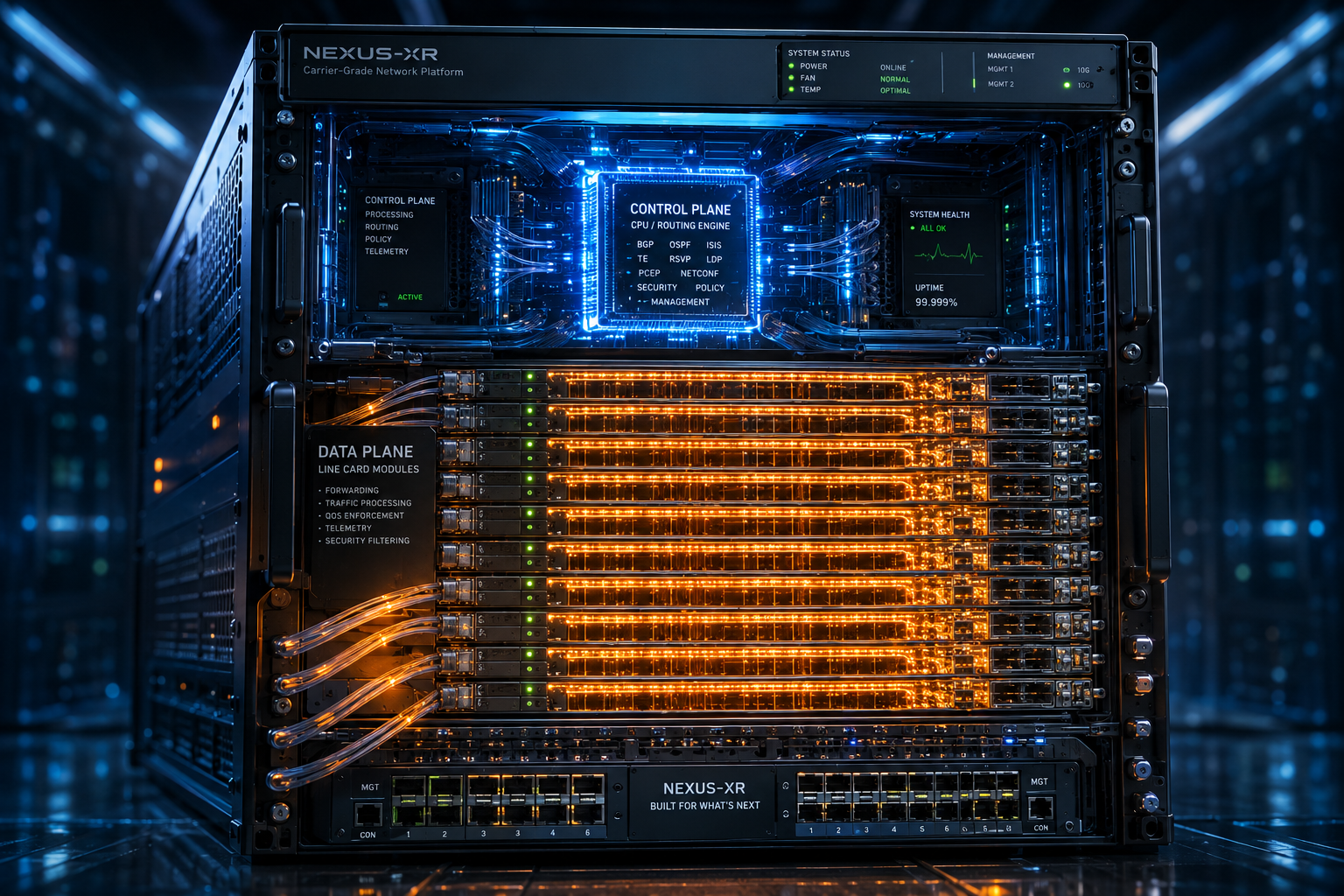
- Control Plane: This layer consists of general-purpose CPUs. Its sole responsibility is to process dynamic routing protocols (BGP/OSPF/IS-IS), maintain the ARP cache, and build the RIB (Routing Information Base). It takes this topological data, calculates the best paths, and compiles it down into the hardware forwarding tables.
- Data Plane (Forwarding Plane): This layer consists of highly specialized ASICs (Application-Specific Integrated Circuits) or NPUs (Network Processing Units) paired with ultra-fast TCAM (Ternary Content-Addressable Memory). TCAM allows the router to search massive routing tables (the FIB - Forwarding Information Base) and evaluate complex Access Control Lists (ACLs) in a single clock cycle, enabling deterministic, wire-speed packet forwarding regardless of how large the routing table grows.
Control Plane Policing (CoPP): This physical separation is vital for survival. While standard transit traffic is handled exclusively by the Data Plane, packets destined to the router itself (such as SSH connections, BGP Hello packets, or ICMP echo requests) must be "punted" to the Control Plane CPU for processing. If an attacker launches a massive direct DDoS attack targeting the router's interface IPs, CoPP rules applied at the Data Plane level strictly rate-limit this punted traffic. This ensures the CPU is never overwhelmed, preventing dynamic routing adjacencies from dropping even while under heavy attack.
Conclusion
The ISP Core is an unforgiving environment where complexity scales exponentially. Mastery here requires moving beyond basic packet routing to understanding advanced BGP manipulation, strict hardware-level isolation, and the absolute necessity of stateful, millisecond-level resilience. When properly architected, this complex synergy of MPLS, TCAM memory, and dynamic routing becomes a silent, indestructible engine powering the global digital infrastructure.